High-temperature piping rarely fails because of one bad component. More often, small design errors combine over time. A rigid clamp, missing guide, or poorly placed anchor can redirect thermal movement into welds, nozzles, and equipment connections. That is why engineers must understand how to select supports for high temperature pipes before reviewing catalogs or drawings. Support selection affects stress, vibration, insulation clearance, maintenance access, and long-term plant reliability.
ASME B31.1 and ASME B31.3 provide the primary code framework for power and process piping design. MSS SP-58 addresses pipe hanger and support materials, design, and manufacturing practices. EPRI technical guidance on high-energy piping also emphasizes flexibility analysis, restraint loads, creep exposure, and inspection planning. These references do not replace engineering judgment. They define the minimum discipline required.
Temperature changes create movement. Steam lines may expand several millimeters between a cold start and full operation. A support that looks suitable in the workshop may bind after insulation, corrosion protection, and thermal growth are added. Field experience matters here. Check the actual pipe route, steel condition, spring travel, and nearby equipment nozzles. Small details matter.
No checklist is perfect.
The ten methods in this guide connect calculations with real installation conditions. They examine material compatibility, load capacity, anchor locations, guides, variable and constant spring hangers, vibration control, insulation space, corrosion risks, inspection access, and lifecycle cost. Some recommendations may need adjustment. That is intentional. High-temperature systems differ widely, and responsible selection requires documented assumptions, qualified review, and periodic reassessment after commissioning.
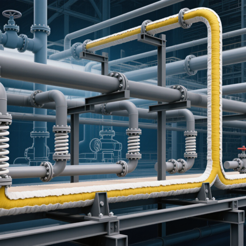
Before selecting supports, define the pipe’s real operating conditions. Record normal, maximum, and minimum temperatures, pressures, flow rates, and fluid properties. Do not rely only on design values. Startup, shutdown, cleaning, and emergency conditions can create different loads. A pipe operating at 480°C may expand several millimeters over a short run. Small changes matter.
Review thermal cycles, vibration, insulation thickness, and nearby equipment connections. Calculate axial growth, vertical movement, and lateral displacement at every support location. Also identify temperature gradients, especially near valves, flanges, and branch connections. These areas often move unevenly. A qualified engineer should verify the calculations against applicable design codes and project specifications.
Field information deserves equal attention. Check pipe guides, anchors, steel structures, and access limits before finalizing the support arrangement. I have seen support drawings appear correct while a beam blocked the expected movement. A neat spreadsheet can still hide a wrong assumption. When data is uncertain, record it clearly and request measurements from operating logs or site inspections. Support materials must also suit the temperature, load, corrosion risk, and insulation design. A support that works during steady operation may fail during repeated thermal cycling. That possibility needs deliberate review.
Selecting supports for high-temperature piping starts with movement, not hardware. NIST thermophysical data places carbon steel’s mean thermal expansion near 11.7 µm/m·°C around moderate elevated temperatures. A 10-meter pipe facing a 400°C rise may grow nearly 47 millimeters. That movement needs a planned path. Fixed anchors, guides, and sliding supports must work together. Otherwise, friction can transfer unexpected loads into nozzles, welds, and equipment foundations. ASME B31.1 and ASME B31J provide recognized methods for evaluating flexibility, stress intensification, and support effects. Field experience also shows a common mistake: supports are often spaced by habit, before thermal movement is calculated.
Load selection requires more than pipe weight. Include the pipe, insulation, valves, fluid, test water, wind, seismic effects, and occasional loads. A hydrostatic test can create a temporary load several times greater than the operating fluid load. Support springs may be necessary where vertical movement changes significantly. Check cold and hot positions. A small error in the assumed anchor point can distort the entire support layout.
Tips: Mark the expected movement beside every support. Confirm guide gaps at operating temperature. Review spring travel, friction, and nozzle loads together. Use project calculations and current code editions, not copied spreadsheets. The design may look efficient, yet one overlooked valve can change it. Recheck questionable assumptions.
Select Support Materials for Temperature and Environmental Resistance
Pipe supports must survive more than the pipe’s stated operating temperature. Check continuous temperature, startup peaks, shutdown cycles, and nearby radiant heat. A material rated for 500°C may weaken under repeated expansion and contraction. Thermal cycling matters.
Choose alloys, ceramics, or engineered composites according to load and exposure. Review tensile strength, creep resistance, oxidation behavior, and allowable stress at temperature. Do not rely on room-temperature data. It can mislead.
Corrosive vapors require additional caution. Moisture, chlorides, sulfur compounds, and cleaning chemicals can attack support surfaces. For insulated pipes, inspect the insulation jacket and vapor barrier. Trapped water can create hidden corrosion beneath the support. That failure is easy to miss.
Match the support with the pipe material. Dissimilar metals may create galvanic corrosion, especially in wet environments. Use suitable isolation layers where necessary. Confirm that pads and liners can tolerate heat without melting, shrinking, or releasing damaging compounds.
Consider fire exposure, ultraviolet radiation, outdoor weather, and mechanical vibration. A support should retain alignment during vibration, not merely carry static weight. Check sliding surfaces around anchors and guides. Thermal movement needs room.
Field experience often reveals small problems. A support may look strong but restrict expansion. Another may work well in dry service and fail near a washdown area. I have seen drawings omit local heat zones. Recheck them.
Use manufacturer data, engineering standards, inspection records, and actual site conditions together. Document the selected material, temperature limits, corrosion assumptions, and inspection interval. Leave room for revision. Operating conditions can change.
Selecting supports for high-temperature pipework starts with the route, not the catalog. Map every elbow, vertical rise, branch, valve, and maintenance opening before selecting support hardware. A straight six-metre run may need sliding supports, while an anchor belongs near a deliberate fixed point. At 450°C, carbon steel can expand several millimetres along a modest pipe run. Direct this movement through guides, rollers, or suitable sliding surfaces. Keep anchors from transferring excessive loads into equipment nozzles. Check operating, shutdown, and hydrotest loads separately. They are rarely identical.
Installation constraints often decide whether a sound design works in practice. A support beneath insulation may require a taller shoe, while limited headroom can rule out a spring assembly. Leave room for welding, coating, bolt tightening, insulation repairs, and future inspection. On crowded racks, a guide may strike nearby steel when the pipe moves. Verify clearances in both cold and hot positions, not only on drawings. Field measurements matter. I have seen calculated supports fail because clamps were installed near welds or guides were set too tightly. Review stress results, support loads, lifting access, and the installer’s actual sequence. No drawing captures every obstruction. Mark uncertain assumptions for site confirmation instead of hiding them inside a neat calculation.
Selecting supports for high-temperature pipes is only half the engineering task. Their performance must be verified during operation. Experienced teams inspect supports under real thermal conditions, not only during a cold shutdown.
Walk the line after startup and record unusual movement, vibration, or contact marks. Check spring supports for travel, corrosion, damaged coatings, and locked settings. Inspect clamps, welds, anchors, guides, and nearby insulation. A bright rub mark may reveal unexpected pipe movement. A tilted support can indicate load transfer or settlement.
Use the piping stress analysis to define inspection points and acceptance limits. Measure support elevation and spring travel with calibrated tools. Compare readings with previous records. Small changes can become serious. Schedule visual checks during routine rounds, detailed inspections during planned outages, and follow-up checks after major temperature changes. Include cleaning around supports, because hidden corrosion often begins beneath insulation or debris.
Maintenance plans should identify responsible personnel, access requirements, measurement methods, and escalation steps. Keep photographs, readings, dates, and operating temperatures in one controlled record. That detail supports reliable decisions. I have seen complete-looking checklists miss a loose guide because nobody inspected it while the pipe was moving. The plan was good on paper, but the field assumption was wrong. Review inspection results with operations and engineering staff, then adjust intervals when conditions change. Some supports need closer attention than others.
Inspection and maintenance planning priorities for evaluating pipe support performance under thermal expansion, sustained loads, vibration, corrosion, and operating movement.
The percentage values are a practical planning allocation for inspection effort, not code-prescribed limits. Final support selection and inspection intervals should be verified against the piping design temperature, calculated loads, thermal displacement, support drawings, applicable engineering codes, and site maintenance procedures.
Record normal, maximum, and minimum temperatures, pressures, flow rates, and fluid properties. Include startup, shutdown, cleaning, and emergency conditions. Small changes can create large loads.
A 10-meter steel pipe may grow nearly 47 millimeters during a 400°C temperature rise. That movement needs a planned path. Check axial, vertical, and sideways movement at every support.
Fixed anchors, guides, and sliding supports must work together. Poor placement can transfer friction loads into nozzles, welds, or equipment foundations. Habit-based spacing is risky.
Include pipe weight, insulation, valves, fluid, test water, wind, seismic effects, and occasional loads. Hydrostatic testing may create a much heavier temporary load. Check both cold and hot positions.
Spring supports help where vertical movement changes substantially during heating. Review spring travel, friction, and connected equipment loads together. A small anchor error can distort the layout.
Check strength, creep resistance, oxidation, and allowable stress at operating temperature. Include startup peaks and repeated thermal cycles. Room-temperature data can mislead.
Moisture, chlorides, sulfur compounds, and cleaning chemicals may attack hidden surfaces. Trapped water beneath insulation can cause concealed corrosion. Inspect jackets, vapor barriers, pads, and liners.
Confirm guides, anchors, steel beams, access limits, insulation thickness, and nearby connections. Mark expected movement beside every support. One overlooked beam can block expansion. I would recheck uncertain assumptions.
Selecting reliable supports is essential for maintaining the safety, stability, and service life of a high-temperature piping system. This guide explains how to select supports for high temperature pipes by first defining operating temperature, pressure, fluid conditions, insulation requirements, and surrounding environmental factors. It then examines thermal expansion, pipe movement, vibration, weight, and other load requirements to determine whether anchors, guides, sliding supports, spring supports, or other configurations are appropriate.
The article also discusses choosing support materials that can withstand heat, corrosion, moisture, and chemical exposure while remaining compatible with the pipe and insulation system. Support designs should match the pipe layout, available installation space, accessibility, and connection details. Finally, proper inspection and maintenance planning are emphasized, including checking for distortion, corrosion, loosened connections, unexpected movement, and changes in operating conditions. A systematic selection and verification process helps reduce stress, prevent damage, and improve long-term piping performance.

Ampy Pipe